Electrical
|
Joined: Jan 2005
Posts: 9,223
Big Bore
|
OP

Big Bore
Joined: Jan 2005
Posts: 9,223 |
Last edited by moe; 05/19/2013 11:53 AM.
|
|
|
Electrical - Battery
|
Joined: Jan 2005
Posts: 9,223
Big Bore
|
|
OP
Big Bore
Joined: Jan 2005
Posts: 9,223 |
From Tinman:
I have found a battery locally that fits our bikes. It's an Interstate battery CYTX12-BS, runs about $60.
Update:
The Interstate Battery website also lists a second battery, the FAYTX12. The online prices seem to be $10-20 more than what your local dealer is getting for them. My local dealer said the difference is the FAYTX12 is all charged up and ready to go. -FriarJohn
Last edited by FriarJohn; 06/24/2009 4:48 PM.
|
|
|
Electrical - Color Schematic & Key
|
Joined: Jan 2005
Posts: 9,223
Big Bore
|
|
OP
Big Bore
Joined: Jan 2005
Posts: 9,223 |
Courtesy of Fishercat and nicely scalable: Color Schematic Three cheers to member birchr (Ray). Schematic KeyAfter clicking above URL, look for the button labeled 'Download This File Now:' near bottom right and click on it. Scroll to 'Download Now:' and click the filename directly below this to download files.
Last edited by moe; 01/29/2009 5:52 PM.
|
|
|
Electrical - Ohm's Law Table
|
Joined: Jan 2005
Posts: 9,223
Big Bore
|
|
OP
Big Bore
Joined: Jan 2005
Posts: 9,223 |
Thanks to BeanoGB, here's the Ohm's Law table: 
Last edited by moe; 10/08/2008 1:01 PM.
|
|
|
Electrical - Fuse Block diagram.
|
Joined: Jan 2005
Posts: 12,877
Should be Riding
|
|
Should be Riding
Joined: Jan 2005
Posts: 12,877 |
Courtesy of Jay. 
Last edited by moe; 10/08/2008 1:04 PM.
|
|
|
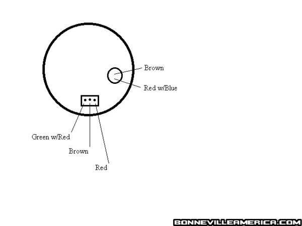
Tach connections in dash.
|
Joined: Jan 2005
Posts: 12,877
Should be Riding
|
|
Should be Riding
Joined: Jan 2005
Posts: 12,877 |
Last edited by moe; 09/19/2008 8:48 AM.
Benny
Black & Silver '02
Too many mods to list
Not enough miles ridden
|
|
|
Driving Light Harness
|
Joined: Jan 2005
Posts: 12,877
Should be Riding
|
|
Should be Riding
Joined: Jan 2005
Posts: 12,877 |
From Soren:
Since i really did't want to slice and dice the factory accessory plug that you use for driving lights, I ordered just the wiring harness for the Triumph driving lights from my dealer. The cost is a hefty $31.70. But I will have the male end of that plug and wires wrapped in a nice harness.
The part number is A9930037.
And here is the schematic for it.

Last edited by bennybmn; 09/18/2006 6:10 PM.
Benny
Black & Silver '02
Too many mods to list
Not enough miles ridden
|
|
|
Rear turn signal to tail/brake lights conversion
|
Joined: Jan 2005
Posts: 4,056 Likes: 78
Loquacious
|

Loquacious
Joined: Jan 2005
Posts: 4,056 Likes: 78 |
Spiffy little kit.. changes your rear turn signals to brake and tail lights. kit
|
|
|
Light bulb numbers
|
Joined: Jan 2005
Posts: 12,877
Should be Riding
|
|
Should be Riding
Joined: Jan 2005
Posts: 12,877 |
Replacement bulb types:
tail light: 1157
Stock turn signals: 1156. --> True replacement 7506 see below
member McSpeedy, "the rear right directional bulb blew. The stock bulbs are stamped [(Wrong #7056) should be 7506] These are 24w bulbs commonly found in some European cars. I brought it to two auto part stores and one cycle repair shop. All they had to offer were 1156 and 1073 which are 12w bulbs. Never guess who had them in stock, WALMART and for about 3 bucks for two. Who da thunk?"
Last edited by moe; 10/08/2008 12:18 PM.
Benny
Black & Silver '02
Too many mods to list
Not enough miles ridden
|
|
|
Re: Electrical - Ohm's Law Table
|
Joined: Jan 2005
Posts: 11,122 Likes: 11
Should be Riding
|
|
Should be Riding
Joined: Jan 2005
Posts: 11,122 Likes: 11 |
Quote:
Thanks to BeanoGB, here's the Ohm's Law table:
Image was moved. Here is the site link
Blowing gravel off rural roads
|
|
|
Re: Electrical - Ohm's Law Table
|
Joined: Jan 2005
Posts: 3,960
Loquacious
|
|
Loquacious
Joined: Jan 2005
Posts: 3,960 |
Ray (birchr) found a short on another members bike that was pretty difficult to find and though he would share with everyone else just in case the problem reoccurs. Quote:
Hi John
Don't know if this may help anyone, but had Biker Benny rang me today as his light fuse kept blowing (Tail & Front) I had remembered reading on here about chaffed wires as they go through the hole in the rear of the headlight. But could not find anything. After taking the tank off etc taking all the connections out of the headlight I isolated it to the speedo.
The little illumination bulbs (push in type) that is held in place by a plastic tie at the bottom of the speedo had come out and the connections were touching. Just thought it may help if someone else has this problem. The bike is an early one as it still has the light switch on the right side, so you can switch the lights off and on..
Ray
John
Like a dog on a car ride with my tongue in the wind
|
|
|
Re: Weak charging system? - the solution
|
Joined: Jan 2005
Posts: 11,122 Likes: 11
Should be Riding
|
|
Should be Riding
Joined: Jan 2005
Posts: 11,122 Likes: 11 |
Last edited by moe; 03/16/2010 10:42 AM.
Blowing gravel off rural roads
|
|
|
Re: Front Turn Signal Connector
|
Joined: Jan 2005
Posts: 11,122 Likes: 11
Should be Riding
|
|
Should be Riding
Joined: Jan 2005
Posts: 11,122 Likes: 11 |
Soren, "I took the turn signal over to Norvac and asked them if they had some of "these" and they said yes. The package is a pack of 10 connectors. The package says: Waldom Molex 03-0601022-p 062 pwr conn recp pnl mnt 2" And then Moe added: Unverified sources for the front turn signal connectors: onlinecomponents.com Part Details Allied Stock #: 863-SPEC Manufacturer: Molex Manufacturer's Part #: 03-06-1022-P Part Description: 062 PWR CONN RECP PNL MNT 2 Allied Electronics www.clickonstock.com
Blowing gravel off rural roads
|
|
|
Re: GPS Power: Auxiliary plug
|
Joined: Jan 2005
Posts: 11,122 Likes: 11
Should be Riding
|
|
Should be Riding
Joined: Jan 2005
Posts: 11,122 Likes: 11 |
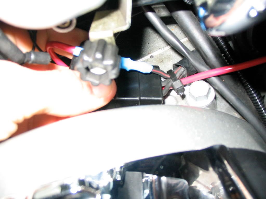
larryshep: Quote:
I have always run mine to the back of the auxiliary power socket. You can buy double 90 degree connectors (Radio shack in the US). Just push them on the power socket, reconnect the plug from the bike wiring harness and connect the leads from the GPS to the connectors.
That way when you stop for gas or whatever you don't have the GPS shut down and have to reboot, as the power socket is 'hot' all the time.
Feb '09 discussion
Blowing gravel off rural roads
|
|
|
Re: Rear Turn Signal Connector
|
Joined: Jan 2005
Posts: 11,122 Likes: 11
Should be Riding
|
|
Should be Riding
Joined: Jan 2005
Posts: 11,122 Likes: 11 |
Zmilin: Quote:
I know you can get the rear connectors from Bellacorse. I've gotten a couple sets just to have. I've never seen that style of connector anywhere else but Im sure its out there somewhere.
In the meantime here's the link: BCC-143 OEM-style Turn Signal Electrical Connectors
Blowing gravel off rural roads
|
|
|
Re: Electrical - Driving lights schematic
|
Joined: Jan 2005
Posts: 11,122 Likes: 11
Should be Riding
|
|
Should be Riding
Joined: Jan 2005
Posts: 11,122 Likes: 11 |
Thanks go to Zmilin 
|
|
|
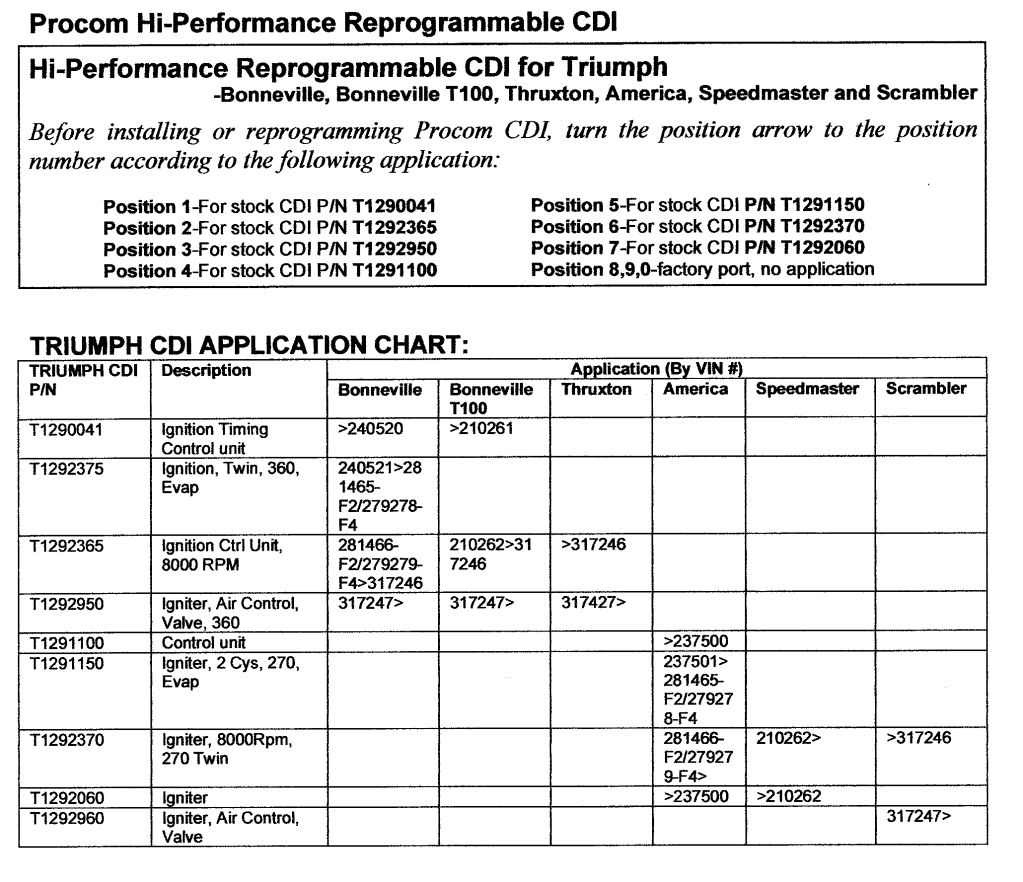
Re: Procom CDI's Position arrow chart
|
Joined: Jan 2005
Posts: 11,122 Likes: 11
Should be Riding
|
|
Should be Riding
Joined: Jan 2005
Posts: 11,122 Likes: 11 |
|
|
|
Re: Wiring relays
|
Joined: Jan 2005
Posts: 4,056 Likes: 78
Loquacious
|
|
Loquacious
Joined: Jan 2005
Posts: 4,056 Likes: 78 |
From Zmilin:  Above is a schematic and pin out for a SPDT (Single Pole Double Throw) relay. Also known as a Bosh relay. I like to use these for higher current loads such as driving lights or heated accessories. You can find these in both 70amp and 30amp. The 30amp is more than adequate for anything you will be doing on the bike. I also like to purchase these with the socket/harness to make wiring easier. Some basics about these relays (referencing the schematic drawing): SPDT Relay (Single Pole Double Throw Relay) an electromagnetic switch, consist of a coil (terminals 85 & 86), 1 common terminal (30), 1 normally closed terminal (87a), and one normally open terminal (87). When the coil of an SPDT relay is at rest (not energized), the common terminal (30) and the normally closed terminal (87a) have continuity. When the coil is energized, the common terminal (30) and the normally open terminal (87) have continuity. How to get them wired up... 1. I like to prep my relay harness first. • If I’m using a socket I remove the wire from the 87A position. Usually a strong tug on the wire is all you need to pull it out completely. • If I’m making my own harness then I just move on to step 2. 2. Next I like to find where my relay will be located and do a temporary mount (tape or zip tie). This way I can route all my wires as needed and make sure none are too short or have tension or worse yet, will be located in a location where they can be pinched or cut. 3. Now I start wiring…. How to wire a 30amp SPDT relay for high current draw accessories with key on activation: • 85 will go to ground. • 86 will go to a wire that activates when the key is in the on position. • 87 will go to my accessory • 30 will go to my battery + terminal. I add an inline fuse* at this wire (NO EXCEPTIONS) in a location that will be easy to reach if needed. * NEVER use a fuse larger than recommended for the accessory. How to wire a 30amp SPDT relay for high current accessories with a toggle switch for activation: • 85 will go to my toggle switch. The other end of the toggle switch will go to ground. • 86 will be connected to 30. o I usually tap 86 to 30 a couple inches down the wire, solder and tape for a clean harness. • 87 will go to my accessory • 30 will go to my battery + terminal. I add an inline fuse* at this wire (NO EXCEPTIONS) in a location that will be easy to reach if needed. * NEVER use a fuse larger than recommended for the accessory. How to wire a 30amp SPDT relay to interrupt the OEM accessory outlet so it is only on when the key is on: • 85 will go to ground. • 86 will go to a wire that activates when the key is in the on position. • Cut the positive wire leading to the accessory port. Connect one end of the cut wire to 87 and the other to 30.
|
|
|
Re: Tech Tip: Measuring Current Draw
|
Joined: Jan 2005
Posts: 4,056 Likes: 78
Loquacious
|
|
Loquacious
Joined: Jan 2005
Posts: 4,056 Likes: 78 |
From Zmilin
I see this subject come up on the forum a lot and there is always a ton of great feedback from members. I thought Id put together a little something as a reference guide when I came upon an article already written. This was geared towards automotive but applies to our world. I pulled out some information that does not apply and added a couple minor things that do apply for us.
I may even do a video to accompany this at some point.
If you’re constantly finding your battery dead after the vehicle sits for a couple days, maybe even just sitting overnight, you might have a current draw. Keep in mind, there are several other factors that might cause a dead battery besides just a current draw. First, you want to check your charging system and make sure there are no problems there. If you still find yourself with a dead battery, you need to start looking for the current draw that is draining your battery. The problem is trying to find what is causing the draw.
What you’ll need
The only tools you will need is a DMM (Digital Multi Meter) and whatever is needed to remove the Negative (-) battery post on your vehicle (wrench, socket, etc.). I would also recommend having a set of “jaw” type accessory probes for your meter. If you don’t have any, you can make yourself some with alligator clips.
How to
Step 1 – Make sure the battery is in working order and is fully charged. Taking current draw readings on a dead battery is a waste of time.
Step 2 – Make sure the vehicle is OFF and all doors are closed. If you have a hood light (or trunk light depending on battery location) you need to fool it into thinking the hood/trunk is closed. For a Motorcycle owner that means all accessories are off.
Step 3 – Loosen the Negative (-) battery terminal, but do not disconnect it.
Step 4 – Prepare the meter for measuring Current per the meter instructions. (WARNING!!! Do not take any Voltage measurements while the meter probes are configured in this position. Doing so can damage the meter!)
Step 5 – Attach the RED probe to the Negative (-) battery post so that you don’t have to hold it. This is easily done with an alligator clip or “jaw” type probe accessory.
Step 6 – With the RED probe secured on its own, hold the BLACK probe tip near the base of the battery post so it does not interfere with the terminal. The object will be to remove the terminal without having to move or reconfigure the BLACK probe.
Step 7 – With your free hand, remove the negative battery terminal while holding the BLACK probe in position on the battery post with your other hand. Optimally you will have a clamp probe accessory on this lead as well that can clamp to the battery post. Allow a little time to pass for the vehicle modules to come to complete rest*. Also known as allowing the modules to go into SLEEP mode. If you are monitoring the Current as this happens, you will see the Current decreasing until it rests at a relatively steady draw. You will then be able to read what your draw is and troubleshoot further from that point.
All vehicles have some form of small or continual (parasitic) current draw. This is caused by things like, clocks or alarm LEDs, etc. All these items need a minimal amount of power all the time to retain their memories, so there’s always a draw. 25-30 mA (milliamp) or less is considered acceptable. It will look like “0.025 A or 0.030 A” on your DMM. Above that, you may have a problem.
If that is the case, start pulling fuses of aftermarket equipment and see if the draw goes away. Car dealerships are well known for blaming aftermarket equipment for this problem, often without ever doing any real troubleshooting, so this is a good place to start. In their defense, most dealership technicians are trained on their brand vehicles and do not even know or understand aftermarket electronics enough to troubleshoot them. If none of your aftermarket equipment is found to be causing the problem, move onto the vehicles fuses.
Changes of 3-5 mA (0.003-0.005) are not necessarily an indicator of something wrong. When you pull a fuse and see a large drop on the meter, that’s when you want to investigate the circuit that fuse was providing power to and find out what is causing the problem. Using this method and testing each fuse (i.e. circuit) one by one, the culprit of your current draw can be found and isolated. You will then need to take whatever actions are needed to fix that problem, but now you know what was causing the problem.[i/]
|
|
|
Re: Tech Tip: Measuring Current Draw
|
Joined: Jan 2005
Posts: 18,825
"Lighten up, Francis."
|
|
"Lighten up, Francis."
Joined: Jan 2005
Posts: 18,825 |
Video on how to use Multimeters, submitted by Keith. http://www.youtube.com/watch?v=bF3OyQ3HwfU
|
|
|
Re: TPS Wiring
|
Joined: Jan 2005
Posts: 11,122 Likes: 11
Should be Riding
|
|
Should be Riding
Joined: Jan 2005
Posts: 11,122 Likes: 11 |
Zmilin:  TPS Wiring Help TPS Wiring Help full thread.
Blowing gravel off rural roads
|
|
|
Re: Electrical Charging Troubleshooting
|
Joined: Jan 2005
Posts: 11,122 Likes: 11
Should be Riding
|
|
Should be Riding
Joined: Jan 2005
Posts: 11,122 Likes: 11 |
Gleaned from varoius post, this thread tosses out some voltage readings at the battery, then goes on to walk us through testing the Alternator/stator/rotor (you choose the term...) From oldroadie  Keith Keith's burned out one 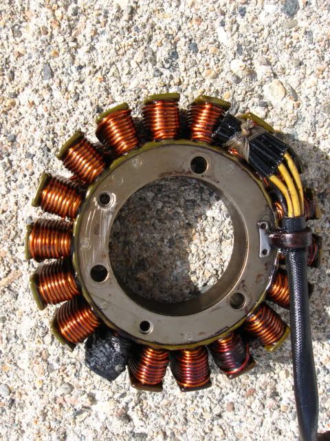 btw kudos to Keith for his work in lighting our path to yota...or is that yogi? And the regulator no picture...  Voltage Readings at Battery Grzegorz’s reading: On the idle at 1000rpm should be at least 14 V Gmike’s readings: Off 12.85 Idle 1000 RPM 13.10 3000 RPM 14.05 From Chy: Alright, a little basic info from my Haynes manual. It says 12.5 volts at idle and 14.5 at 4000 rpm's. Voltage at the Alternator connector at 4000 rpm's should be 60 or 70 volts ac... if "much less" check the alternator. It goes on to say that there are no checks for the Regulator/rectifier, if possible replace it with a known good one. No real specs on the alternator windings except that they should be a "low" resistance reading between all terminals and that none should have continuity to ground. That's pretty much it for Mr Haynes.. hope some of it helps. Before you do anything else, check your fuse panel. Fuse no 11 might be burnt. The regulator feeds the battery through that circuit. Check your other fuses while you are at it. From midnight7503: I take it the 03 models have the wiring running under the carbs? my 06 runs down under the motor, so only slightly different trace the wires from the cover of the rotor (alternator) to the joiner before the regulator, run a multi meter across the 3 wires in turn pairing them up, on the rotor side, start the motor and rev to around 4000rpm and and note the readings, this is where you should get a reading of between 60-70 volts, if its lower then you know where your problem is, if it is between that, then it may be your regulator. EDITOR: Look under your saddle for the connector or joiner as midnight7503 calls it. The photo below is of Keith's joiner/connector. 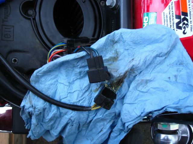 Decosse: Decosse:Before you start it: First, that connector above is the one I wanted you to inspect to look for any signs of burning/damage (also - how did the connector the R/R plugged into look?) Next, at same connector, do the test I outlined parenthetically below - measure the resistance between any of the three pins (does not matter which one) to engine ground - should be 'open' i.e. infinite resistance. (unplug the stator and measure resistance between any one of the three terminals in the connector [end that goes back to the stator, NOT the R/R] and engine ground - that should be open circuit, infinite resistance. If you measure short (zero ohms) then your stator is 100% to be bad. Conversely, if 'open', not absolute guarantee is good, but high probabilty it is OK. ) If that is good (i.e. not short) then you can start it; with meter on AC Volts measure from pins 1-2, 2-3 and 3-1 in turn (doesn't matter which you call 1 etc) All three should the same at any given rpm - at idle expect ~ 20V. As you increase rpm the voltage should rise, but again, if you fix the rpm (say 4000 rpm), all three should be the same - the absolute numbers are less important, that they are balanced is what indicates one leg is not 'down'. Again, if you get a 'short' in the first (resistance)test, don't even bother starting it.  LINKS Electrical charging issues... Electrical blues HELP! getting a charge out of your BA/Speedy Re: Weak charging system? - the solution
Blowing gravel off rural roads
|
|
|
|
|